2018: Challenge 5

Automated in-situ Defects Detection in Powder Bed Metal Additive Manufacturing Parts

Additive manufacturing (AM) is the ability to deposit materials layer-by-layer or point-by-point to fabricate complex components directly from computer-aided design models. Although AM technologies have demonstrated the ability to fabricate complex geometries capable of achieving improved performance characteristics, few AM components are currently being used in production environments, mainly due to the challenges and costs associated with the certification and qualification of components. The current state of the industry is to certify components by using expensive methods such as computed tomography or mechanical testing, but their cost is working against the business case for AM components. An alternative method is to take a data driven approach to fully understand how the series of interconnected material deposition/melting events results in specific spatial material properties and/or defects. This imposes to create first a digital twin of the additive part as we built it using in-situ measurements and then to use data analytics techniques to learn from such data. This concept is the foundation of the Data Analytics Framework for Manufacturing that the ORNL Manufacturing Demonstration Facility (MDF) is actively developing to address the certification and qualification problem.

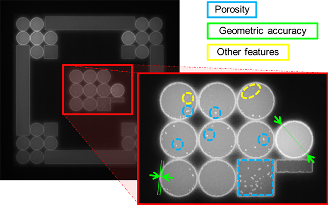
As part of this framework, the proposed data challenge focuses on the detection of specific defects in parts manufactured using an electron beam powder bed system, the ARCAM Q10 machine, (http://www.arcam.com/technology/products/arcam-q10/). To understand how the powder bed melting process works, please refer to this video: https://www.youtube.com/watch?v=M_qSnjKN7f8). For this challenge we are mainly interested to quantitatively assess the geometric accuracy of the part and the presence of failure points such as porosity, swelling, cracks, delamination, and lack of fusion. The importance of detecting defects in-situ is twofold: (1) detected early they can eventually be corrected on the fly with a feedback loop control mechanism, hence insuring a higher manufacturing success rate; and (2) these defects can be used as criteria to discard or to accept a part if the intended use of such is or not compromised. Either option will help circumvent the need for expensive testing. On the Q10 system, hundreds of heterogeneous sensing modalities are monitored to ensure the machine operation. Amongst them, for in-situ quality control, the ARCAM Q10 machine is equipped with a near-infrared sensitive camera capturing an emissivity map of the powder bed once a layer is completed. Each image (see Figure 1) shows variations in pixel intensities as a function of temperature, variations indicative of the presence of a feature of interest.

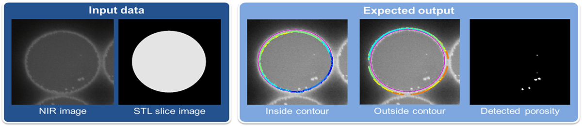
The dataset provided was created using the Dream3D open source platform. It includes an HDF5 file with the extension “.dream3d” and “.xmdf” files that can be used in Paraview to visualize the data. The dataset contains one data container per additive part, and each data container contains multiple attribute matrices, one for each modality of the digitized version of the build. For this challenge, we have only included two image modalities:

  • STL slices images: additive parts are printed by stacking up slices extracted from the source CAD file. We have recorded for each layer the corresponding slice, extracted at the desired height as a black and white image, where white regions correspond to the intended printed regions and black region should not be printed. Note: there is an antialiasing effect around the contours (at the transition black/white).
  • near infrared images: they represent the emissivity measurement at the end of the print for each layer. In Figure 1, porosity appears as bright dots of various sizes, the printed contours (white curvilinear shapes) are delineating homogeneous grey regions corresponding to the infill melt areas, form the unmelted black region. As a rule of thumb, any disturbance of the grey region corresponds to a defect. Going through the entire stack of NIR images one will notice that the grey value within a region is almost never the same throughout the height of a part. This is caused by the scan strategy optimization for each layer which make the electron beam visit the same area at different times when building up. As a result, the thermal emissivity varies, hence the change in measurement
    Each attribute matrix holds a stack of thousands of images registered in space. The dimensions of the 3D stack, its resolution and its position in space are recorded in the dream3d file.

Challenge Questions: we are proposing five challenge questions, ranked by complexity:

  1. Delineate the inside contour of each part: for each part delineate the interior region with subpixel accuracy
  2. Detect and map all defects present in each part: identify non-uniform pattern in the melted region, without necessarily labeling them one of the aforementioned defects of interest.
  3. Detect and map porosity: porosity is one of the most critical defect to identify. Building upon question 2, implement a classification mechanism to distinguish between pores and the other defects
  4. Delineate the outside contour of each part: delineating the outside contour can be more challenging when two objects are close to each other. Your solution from question 1 will most likely have to be adapted to achieve subpixel location of the outside contour.
  5. Implement a solution that can delineate the outside of each contour and map porosity for each layer with the computing time under one second: there is approximately 5 seconds between the capture of the NIR image and the beginning of the next layer. In the scheme of a feedback loop control implementation, the detection of major defects should be completed before the next layer start in order to implement corrective actions. Therefore, the geometric accuracy assessment and porosity map should be completed in maximum one second, to leave time for the system reconfiguration.
  6. (optional) we will offer to benchmark the algorithm against at least one dataset from a similar build for which we have high resolution CT of the parts showing the exact location of pores. The results will be provided to the participant to include in their final submission.

There are non-constraints on the type of technique to use to process the data, anything ranging from image processing, statistical analysis, machine learning, etc. is welcome.


Dataset Name: Dream3D Data

Download Datasets

Download PDF
SMC2018-DataChallenge-05


XXXXXXXXX
Figure 1: Near infrared image of the powder bed and close-up view of defects of interest.

XXXXXXXXX
Figure 2: Example of expected result for a selected region of interest. (input data) images of the cross section of a cylinder in the NIR data and the corresponding STL slice, (expected output) the magenta line in the first two images represent the intended location of the contour (contour of the STL slice). A series of dots for each contour point was places inside and outside the melted contour to show the deviation between intent and execution. The final image shows the porosity map in this layer for this object.